How To Choose Profile
Aluminium Profiles & Accessories » Aluminium Profiles
CHOOSING THE CORRECT ULTRAXIS PROFILE FOR YOUR APPLICATION
These instructions will aid the selection of a Ultraxis Profile when a point load is applied. Steps A to E refer to paths which should be followed on the diagram opposite. The paths will confirm or deny an estimate of the correct Ultraxis Profile for any given application.
For calculation of other loading types please refer to relevant mechanical texts.
The diagram is a graphic representation of the deflection calculations here
It will be necessary to differentiate between the three loading types:
| 1. | Cantilever Load (Rigidly fixed one end) |
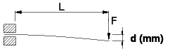 |
1 |
| 2. | Simply Supported |
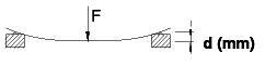 |
2 |
| 3. | Rigidly Fixed Both Ends |
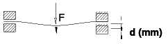 |
3 |
Procedure for determining the deflection of an Ultraxis Profile when the following details are known:
Applied Load, Unsupported Length, and Selected Profile Size (an estimate will need to be made of the most suitable size at this stage
Find the applied load on the Y1 axis. Draw a horizontal line from that point across the graph
Now find the unsupported length L on the X-axis. From this point, draw a vertical line upwards through the graph
Find the intended section Moment of Inertia on the Y2 axis (values for Ultraxis Profile standard sizes are shown in the table to the right of the graph). From this point, draw a second horizontal line across the graph
Draw a line through the intersection of the lines A & B, parallel to the diagonal lines running across the graph and intersect this new diagonal with line C
From the point at which line D intersects with line C, draw a vertical line up thr graph; this line should cross through the relevant logarithmic scale (load type 1, 2 or 3 above). The deflection for the given loading condition can now be read from the scale
Steps A to E may also be used in a variety of sequences, depending on the variables shown. See below:
To find the optimum Ultraxis Profile size when Maximum Deflection, Applied Load and Unsupported Length are know, use the following sequence:
| A | B | E | D | C |
|---|
To find the Maximum Load for a given profile size, when Maximum Deflection and Unsupported Length are known, use:
| C | E | B | D | A |
|---|
To find the Maximum Load for a given profile size, when Maximum Deflection and Applied Load are known, use:
| C | E | A | D | B |
|---|